Wednesday, 9 October 2013

Static Routes - Basic Setup

This lesson will illustrate the necessary steps to configure a simple static route on a typical Endian appliance. This will allow us to configure routing (i.e. communication capabilities) between the Endian and other networks that may not live directly on the Endian but on an external router or through a VPN tunnel.

Configuration Example

?name=Network_Diagram_-_Static_Routes.png
In this simple example, we'll configure a static route to an external network that lives on a router within the Green network. As you can see the router has one interface in the Green network and another interface for the external network that lives outside the Green network.

Create Static Route

?name=media_1303153399259.png
Now we'll add a static route in the Endian under Network > Routing > Static Routing. Here we'll leave the "Source Network" field blank to mean ANY and then supply the destination network (external) and the route gateway IP which is the Green IP of the external router.
Click Add Route and then Apply to complete the process.

Verify Route

?name=media_1303153732276.png
Now you can verify the route works properly by pinging a device in the remote network (10.45.1.0/24) and vice versa. Be sure to check the appropriate firewall rules are in place to allow the desired level of communication between the two networks.

Policy Routes - Basic Outbound Load Sharing:

This lesson will illustrate the necessary steps to configure a simple static route on a typical Endian appliance. This will allow us to configure routing (i.e. communication capabilities) between the Endian and other networks that may not live directly on the Endian but on an external router or through a VPN tunnel.

Configuration Example

?name=Network_Diagram_-_Policy_Routes.png
In this simple example, we'll configure policy routing so that the Green (LAN) and Orange (DMZ) use the primary Internet connection while the Blue (WIFI) network uses a secondary Internet connection This will ensure our Blue (WIFI) users will not take bandwidth from the Green / Orange network traffic.

Create Policy Route #1 (Green / Orange)

?name=media_1303154246892.png
Now we'll add a new policy route in the Endian under Network > Routing > Policy Routing. Select the GREEN and ORANGE zones as the Source and we'll leave the Destination network / ports blank ( = ANY) and then configure the route to use the Main Uplink. Notice we've checked the "Use backuplink if uplink fails" as this will provide a failover policy to the backup uplink in the event our main uplink goes down.
Click Create Rule and then Apply to complete the process.

Create Policy Route #2 (Blue)

?name=media_1303154490152.png
Now we'll add our second policy route in the Endian for the Blue network. Select the BLUE zones as the Source and we'll leave the Destination network / ports blank ( = ANY) and then configure the route to use the Backup Uplink. Notice we've checked the "Use backuplink if uplink fails" as this will provide a failover policy to the main uplink in the event our backup uplink goes down.
Click Create Rule and then Apply to complete the process.

Verify Routes

?name=media_1303154592110.png
Now you can verify the route works properly by performing a traceroute from any workstation in the Green / Orange network to the Internet and you should see the packet leave out of the Main uplink. Then you can do another traceroute from any device in the Blue network to the Internet and you should see that packet leave out of the Backup uplink.

Endain SNAT (Source NAT) - Basic Setup

This lesson will illustrate the necessary steps to configure a very simple Source NAT (SNAT) on a typical Endian appliance. The primary purpose of Source NAT is to take an internal application (IP and port) and manipulate which external IP and/or port is masqueraded to the Internet. By default, the Endian will masquerade all outbound connections to the primary Red interface IP address so you need SNAT in instances where you don't want this to occur.

Configuration Example

?name=Network_Diagram_-_SNAT__Simple_.png
In this simple example, we'll setup a Source NAT (SNAT) for an mail server in the Orange (DMZ) network. We'll use one of our (non-primary) statically assigned public IP addresses as our masqueraded IP.

Create SNAT Rule

?name=media_1300822101219.png
We'll begin by creating a new SNAT rule at which point we can configure all the necessary fields to correspond to our example network. Notice in the "NAT to source address" dropdown we specifically select our new public IP address to use for masquerading for this rule.
Once done, click the Create Rule button.

Apply the Rule

?name=media_1300822223616.png
Once your rule is created, you must apply the rule to the device by clicking the Apply button (shown above).

Verify the Rule

?name=media_1300822266066.png
Now that our rule has been applied successfully, we can test that our mail server is being masqueraded to the correct IP address.

Note

You can test a Source NAT rule from any server with a browser by using a site like WhatIsMyIP which will tell you what which public IP you're coming from.

Endian Network Configuration Wizard

This lesson will illustrate the steps necessary to configure all of the network interfaces of the Endian appliance after the initial configuration.

Endian Network Architecture

?name=media_1295470572751.png
Before we begin the configuration process, please take a moment to familiarize yourself with the color-coded network zones available in the Endian platform and how they are intended to be used (pictured above).

Choose RED (WAN) Interface Type

?name=media_1295300780537.png
The first step is to choose the connection type of your primary WAN interface. In most cases the proper selection is either Ethernet Static or DHCP unless you require one of the other specific connection types. Click the Forward button to continue.

Note

If you require a configuration where you will not need a Red (WAN) interface, you can select Gateway as the connection type and this will allow you to deploy the Endian in a semi-transparent configuration. This option will allow you to deploy the Endian into a network using the Green (LAN) interface as your primary network connection and using an existing gateway that lives within the Green network.

Add Network Zones

?name=media_1295302204951.png
The next option will allow you to select any additional network zone you wish to have configured on your Endian appliance. The available options will depend on the total number of available Ethernet NIC's on the Endian device. Your options could include adding the Blue zone (Wifi) or Orange zone (DMZ) or both. Click the Forward button to continue.

Configure Network Zones

?name=media_1295467280490.png
The next step involves configuring the actual IP address you want assigned to the Endian device for each existing network zone. The default Green IP is provided for you but you can use any IP address and subnet you wish. You are also allowed to add additional networks that may co-exist within each single network zone. An example of where this might be used is if you host multiple internal subnets that all need to exist within the same network segment (within one zone).
The next item is a graphical representation of the available physical network interfaces and which zone they are mapped to. You may check or uncheck one or more network interfaces to belong to a network zone (at least one is required) and you may have more than one physical interface per zone; however, you cannot have one physical inteface belong to more than one zone. A network zone with multiple network interfaces will act as a bridge and mimic the behavior of a switch though using an actual physical switch is recommended where performance and efficiency are desired. Next to each network interface port is (1) the link status which indicates if there is a device actually connected to the port, (2) NIC device driver description, (3) network MAC address, and (4) the operating system physical device name.
The last two items are the host and domain name you want assigned to the Endian device itself. Click the Forward button to continue.

Note

It is suggested to follow the standards described in RFC 1918 and use only IP addresses contained in the networks reserved for private use by the Internet Assigning Numbers Authority (IANA):

  • 10.0.0.0 - 10.255.255.255 (10.0.0.0/8), 16,777,216 addresses
  • 172.16.0.0 - 172.31.255.255 (172.16.0.0/12), 1,048,576 addresses
  • 192.168.0.0 - 192.168.255.255 ( 192.168.0.0/16), 65,536 addresses
The first and the last IP address of a network segment are the network address and the broadcast address respectively and must not be assigned to any device.

Configure Red (WAN) Interface

?name=media_1295469370723.png
Now you can configure the Red (WAN) interface according to your ISP connection type (as selected during Step 1). The configuration is identical to the previous step where you must configure the IP, subnet, and gateway (if necessary), select the appropriate physical inteface to use for the Red (WAN) connection, and fill out any other ISP connection specific fields.
If you have multiple public IP addresses assigned, you may enter each IP in the "Add additional addresses" field (1). You should list each individual IP in either IP/Netmask or IP/CIDR format with one entry per line (Example: 29.150.10.5/24, 29.150.10.6/24, ...)
The options for MTU is to manually enter a custom value for interface MTU size and is not recommended unless instructed by your ISP. The option to Spoof MAC address with is really only useful for situations where your ISP modem has a "sticky" connection and requires that your Internet MAC address always stay the same. This option would allow you to configure the Endian to "forge" it's Red interface MAC address so you do not lose your ISP connection.
Click the Forward button to continue.

Configure DNS

?name=media_1295469864611.png
This option is only required if you are not using some form of DHCP for your Red (WAN) connection. You should fill in your ISP-provided or preferred public DNS servers in these fields. Click the Forward button to continue.

Setup Email Information (Optional)

?name=media_1295469939589.png
Here you can provide the administrator (recipient) email account along with the Endian (sender) address you want emails from the Endian firewall to use. Also you may specify the address of an email smarthost should you require one. Click the Forward button to continue.

Apply Configuration

?name=media_1295470079852.png
The last step is to apply the configuration to the device. Keep in mind, the changes you made may take up to 20 seconds to be fully applied to the device and for dependent services to be restarted so this may impact any internal device(s) ability to access the device or pass traffic through it. You must access the administration interface of the Endian device using the new IP settings either manually or using the link in the Web UI provided.

Endian Web Proxy - Basic Setup (Transparent)

This lesson will illustrate the necessary steps to configure a very simple transparent web proxy on a typical Endian appliance. A transparent web proxy is one that requires no client-side changes to operate effectively (all traffic is tranparently redirected). The primary purpose of the web proxy is to (1) allow for a simple method to filter web traffic to appropriate levels for business and (2) provide accountability for user web traffic.

Enable the Web Proxy

?name=media_1300829038816.png


The first step is to enable the web proxy by clicking the gray button (which will turn green when enabled). Once this is done, we can configure the networks we want to be filtered transparently (using Green only in this example).

Configure the Log Settings

?name=media_1300828798973.png
Since we want to have all web access (allowed and blocked) logged for review purposes, we're going to enable the appropriate logging options.
Click Save and then Apply the changes to proceed.

Configure the Content Filter Profile (Default)

?name=media_1300829711111.png
In this example, we're only going to configure web filtering by URL Blacklist (only) for ease and administration purposes. The first thing we'll do is ensure our HTTP antivirus is enabled by checking the appropriate box. You can select the whole category to block by clicking the green arrow or, alternatively, you can drop down the subcategories and select those individually in order to block some and not others. You can also attach custom white- or blacklists to this profile as well.
Click Update Profile and then Apply the changes to proceed.

Note

When you enable web filtering by phrases (Content Filtering) this will block those categories of phrases for content "inside the page" which will result in a more aggressive blocking strategy with potentially a higher false positive rate.

Configure the Access Policy

?name=media_1300829958665.png
The last step is to create an access policy which will map the content filtering profile based on a specific network configuration. In the example above, we're creating a simple policy for the Green zone (entire network) that is using the content filtering profile (default) that we just configured in the previous step.
Click Create Profile and then Apply the changes to finalize the configuration.

Test the Web Proxy

?name=media_1300831781271.png

You can test your configuration now by browsing the Internet from the Green network and you should see a block page on sites that match the categories selected.

Verify Logging

?name=media_1300832018560.png

Monday, 7 October 2013

How to Install Endian Software Firewall


Installation of Endian Community Firewall 

Endian Firewall Community Edition
I’ve been meaning to set up my personal router/firewall for some time now. Currently I’m using your standard off-the-shelf Linksys router to run my network. This being my first home setup I don’t have anything else to compare it to other than a few commercial routers and firewalls. The following is a how-to for the installation and configuration of Endian Firewall (Community Edition), along with explanations on what some setting mean.
Installation:
Boot up is your typical Linux distribution. Once booted up the first screen you come to is the language selection. There are only three languages available: Deutsch, English, Italiano. I’ve selected English.

 Next is confirmation that you want to install the software and where it will be installed. Say “yes” to continue.


 Do you want to enable console over serial. This setting is if you want to be able to locally administer the firewall. This is ideal if you forgot your password and want to reset the password.


Next is the Appliance Installer, this may take a while depending on how fast the transfer is between the installation media and the hard drive.

Configure the GREEN interface. This is the interface that is on your internal network and allows you access to configure the firewall.

Installation is finished. It is important to write down the following address: http://efw-community and https://efw-community:10443 . After selecting “OK” the system will restart.

Boot Progress

This is the menu you are presented with after the system is completely booted. At this point you can remove your keyboard, mouse and monitor. You will be able to do the rest of the configuration remotely. You will configure the passwords through the GUI interface.

To connect to the GUI I started up FireFox (any browser should do) and typed in the address of the machine using https and was presented with this. Select “I understand the Risks.”


Click on “Confirm Security Exception.”

You are now at the Welcome Screen of your firewall.


Monday, 26 August 2013

How to add VMWARE ESXi 5.1 host to vCenter Server ?

Once you have installed the VMware ESXi 5.1 server, you need to add the server to existing VMware vCenter server to manage it .You can not use the VMware ESXi 5.1 host without adding to vCenter server.Once you have added the ESXi host to vCenter server, you can start creating  a virtual machines using the vSphere Client.In these virtual machines ,you can install most of the windows server operating systems,various Linux operating systems and Solaris X86 operating systems.
This article explains about how to add the ESXi 5.1 host to existing vCenter Server 5.1.
1.Open a VMware vSphere client 5.1 and connect to the vCenter server.


2.After logging to vCenter server ,you can see the below screen with instructions of adding ESXi hosts.
3.Create a new Datacenter to add the ESXi hosts in to that.The datacenter is nothing but collection of ESXi hosts. If you have ESXi hosts on different locations,Provide the meaning full name to the datacenter in vCenter.

4.Now our datacenter is ready .Here the datacenter name is UnixArena-DC .
5.Click on the "Add a host " link.Here you provide the ESXi host details and valid credentials to add it in vCenter. Click Next to continue.

6.In this screen you will get the summary of ESXi 5.1 host details and it's virtual machines.
Here i don;t have existing virtual machines on ESXi 5.1 host.
7.Add the valid license key .If you don't have a valid one ,just click next to continue to in Evaluation mode.

8.If you want to restrict remote users directly logging to this host,just enable lockdown mode.

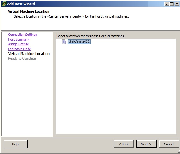
9.Select the virtual machines datacenter locations.

10.Click finish to complete the setup.
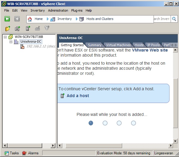
11. vCenter will take some time to add the ESXi host.Be patience.

12.You have successfully added the ESXi host to vCenter server.Click on "Create a new virtual machine" to create new virtual server.
13.The below screen shows configured virtual machine with the name "Solaris 11- UnixArena" .
Thank you for reading this article.