Friday, 4 February 2022

YumRepo Error: All mirror URLs are not using ftp, http[s] or file in Cent Os 6

Error

[root@localhost ~]# yum update
Loaded plugins: fastestmirror
Loading mirror speeds from cached hostfile
YumRepo Error: All mirror URLs are not using ftp, http[s] or file.
 Eg. </html>/
removing mirrorlist with no valid mirrors: /var/cache/yum/i386/6/base/mirrorlist.txt 

Error: Cannot find a valid baseurl for repo: base

Fix

Be sure that you can ping vault.centos.org


Then edit /etc/yum.repos.d/CentOS-Base.repo


Comment out mirrorlist and uncomment baseurl


Change all


baseurl=http://mirror.centos.org/centos/$releasever/centosplus/$basearch/

to


   baseurl=http://mirror.nsc.liu.se/centos-store/6.10/os/$basearch/


yum clean all

yum update -y 

Enjoy!!!!

Saturday, 5 June 2021

Extending a logical volume in a virtual machine running Red Hat or Cent OS

To extend the logical volume:

Recommends taking a complete backup of the virtual machine prior to making these changes.

 This provides steps for extending the root partition residing in a logical volume created with Logical Volume Manager (LVM) in a virtual machine running Red Hat/CentOS

My Virtual mechi have only 20GB I have incread to 40 GB like as below screenshort.

1.         Power off the virtual machine.
2.         Edit the virtual machine settings and extend the virtual disk size. (Refer to the above picture)
3.         Power on the virtual machine.
4.         Identify the device name, which is by default /dev/sda, and confirm the new size by running the command:

fdisk -l


Create a new primary partition:

1.         fdisk /dev/sda (depending on the results of step 4)

2.         Press p to print the partition table to identify the number of partitions. By default, there are 2: sda1 and     sda2.

3.         Press n to create a new primary partition.

4.         Press p for primary.

5.         Press 3 for the partition number, depending on the output of the partition table print.

6.         Press Enter two times.

7.         Press to change the system's partition ID.

8.         Press 3 to select the newly creation partition.

9.         Type 8e to change the Hex Code of the partition for Linux LVM.

10.     Press to write the changes to the partition table.

11.     I have done the above points. See the 2 screenshots below for our reference


 Increasing the logical volume

We use the pvcreate command which creates a physical volume for later use by the logical volume manager (LVM). In this case, the physical volume will be our new /dev/sda3 partition.


Next, we need to confirm the name of the current volume group using the vgdisplay command. The name will vary depending on your setup, for me it is the name of my test server. vgdisplay provides lots of information on the volume group, I have only shown the name and the current size of it for this example.


Now we extend the ‘vg_ibikz’ volume group by adding in the physical volume of /dev/sda3 which we created using the pvcreate command earlier.


Using the pvscan command we scan all disks for physical volumes, this should confirm the original /dev/sda5 partition and the newly created physical volume /dev/sda3


Next, we need to increase the logical volume (rather than the physical volume) which basically means we will be taking our original logical volume and extending it over our new partition/physical volume of /dev/sda3.

Firstly confirm the path of the logical volume using lvdisplay. This pathname will vary depending on your setup.

The logical volume is then extended using the lvextend command.


There is then one final step which is to resize the file system so that it can take advantage of this additional space, this is done using the resize2fs command for ext-based file systems. Note that this may take some time to complete, it took about 30 seconds for my additional space.


Alternatively, if you’re running the XFS file system (default as of RedHat/CentOS 7) you can grow the file system with “xfs_growfs /dev/vg_ibikz/Iv_root”.

That’s it, now with the ‘df’ command, we can see that the total available disk space has been increased.


Summary

With this method, we have increased the virtual disk drive through VMware, created a new partition out of this newly unallocated space within the guest OS, turned it into a physical volume, extended the volume group, and then finally extended the original logical volume over the newer physical volume resulting in overall disk space being increased successfully.


Wednesday, 19 February 2020

Cisco ASA Commands for IPsec VPN

  1. show vpn-sessiondb detail l2l
  2. show vpn-sessiondb anyconnect
  3. show crypto isakmp sa
  4. show crypto isakmp sa
  5. show run crypto ikev2
  6. more system:running-config
  7. show run crypto map
  8. show Version
  9. show vpn-sessiondb license-summary
  10. show crypto ipsec stats
  11. capture test interface inside match ip host x.x.x.x host y.y.y.y

  12. X-Source
  13. Y-Destination

  14. show capture test1

  15. no capture test1

Cisco ASA Site-to-Site IKEv1 IPsec VPN Dynamic Peer

Phase 1 Configuration:


ASA1 & ASA2
(config)# crypto ikev1 policy 10
(config-ikev1-policy)# authentication pre-share
(config-ikev1-policy)# encryption aes
(config-ikev1-policy)# hash sha
(config-ikev1-policy)# group 2
(config-ikev1-policy)# lifetime 3600
ASA1 & ASA2
(config)# crypto isakmp identity address 
(config)# crypto ikev1 enable OUTSIDE
ASA1(config)# tunnel-group DefaultL2LGroup ipsec-attributes 
ASA1(config-tunnel-ipsec)# ikev1 pre-shared-key MY_SHARED_KEY
ASA2(config)# tunnel-group 10.10.10.1 type ipsec-l2l
ASA2(config)# tunnel-group 10.10.10.1 ipsec-attributes
ASA2(config-tunnel-ipsec)# ikev1 pre-shared-key MY_SHARED_KEY

Phase 2 configuration

(config)# crypto ipsec ikev1 transform-set MY_TRANSFORM_SET esp-aes-256 esp-sha-hmac
ASA1(config)# access-list LAN1_LAN2 extended permit ip 192.168.1.0 255.255.255.0 192.168.2.0 255.255.255.0
ASA2(config)# access-list LAN2_LAN1 extended permit ip 192.168.2.0 255.255.255.0 192.168.1.0 255.255.255.0

Tuesday, 19 June 2018

Create a network security group using the Azure portal

You can use an NSG to control traffic to one or more virtual machines (VMs), role instances, network adapters (NICs), or subnets in your virtual network. An NSG contains access control rules that allow or deny traffic based on traffic direction, protocol, source address and port, and destination address and port. The rules of an NSG can be changed at any time, and changes are applied to all associated instances.

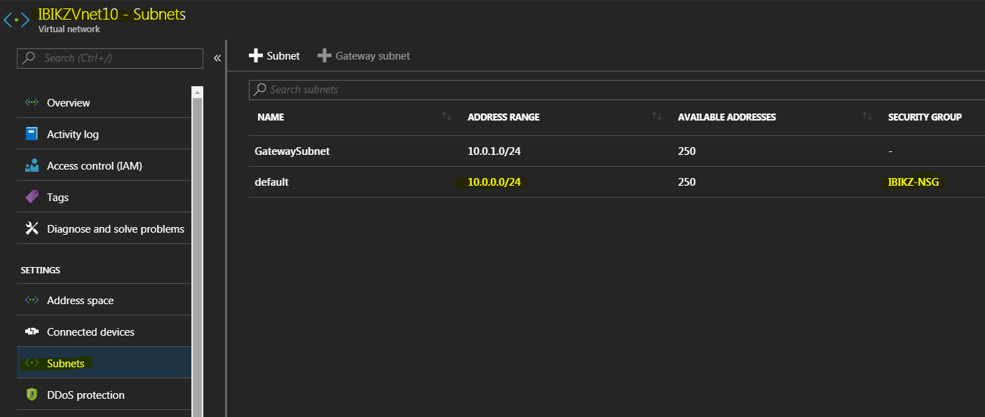
In this scenario, you create an NSG for each subnet in the IBIKZVnet10 virtual network, as follows:


Create the IBIKZ-NSG (NSG)

To create the IBIKIZ-NSG NSG as shown in the scenario, complete the following steps:


Create rules in an existing NSG


To create rules in an existing NSG from the Azure portal, complete the following steps:

  1. Select All Services, then search for Network security groups. When Network security groups appear, select it.
  2. In the list of NSGs, select IBIKIZ-NSG > Inbound security rules
  3. In the list of Inbound security rules, select Add.


4.Under Add inbound security rule, create a rule named web-rule with the priority of 200 allowing access via TCP to port 80 to any VM from any source, and then select OK. Notice that most of these settings are default values already.

5, After a few seconds, you see the new rule in the NSG.


Associate the NSG to the IBIKZVnet10 subnet


  1. Select All services >, enter Resource groups, select Resource groups when it appears, then select RG-NSG.
  2. Under RG-NSG, select ... > IBIKZVnet10

3,Under Settings, select Subnets > FrontEnd > Network security group > IBIKZ-NSG.


4, In the FrontEnd blade, select Save.


Monday, 18 June 2018

Connect Two Azure Resource Manager Virtual Networks Using VNet Peering

In this post I will show you how to link two virtual networks using VNet Peering, a new feature in Microsoft Azure.


What Is VNet Peering?

VNet Peering is the easiest and best-performing way to connect two virtual networks (VNets). The alternative, VNet-to-VNet VPN, requires that you deploy gateways in each of the connected VNets. Then you must create a VNet tunnel between the two VNets. Because you must use a gateway, the VPN option limits network speeds between the VNets to the bandwidth capabilities of the gateway — 80 Mbps in the case of a Basic gateway (not 100 Mbps as often documented).
 VNet peering links VNets using the underlying software-defined network, tunnelling packets across the physical data centre networks using NVGRE. This means that you don’t need a gateway and that two virtual machines in different VNets can communicate at the speed of their NICs (that’s going to be around 25 Gbps for some machines once a current hardware offload preview goes generally available).

Limitations of VNet Peering


My approach to linking VNets is that I always want to use VNet Peering, but there are times that I must fall back to using VNet-to-VNet VPN. Here are some of the requirements and limitations of VNet Peering:

  • VNets in different regions: VNet Peering requires that both VNets must be in the same Azure region.
  • Network addresses: The IP address spaces of both VNets must not overlap.
  • No A-B-C links: There is no implied transitive linking of VNets. If you link VNet A to VNet B, and VNet B to VNet C, there is no implied routing from VNet A to VNet C. This would require the use of network virtualization appliances to act as routers, or that you peer VNet A with VNet C.
  • Across-subscriptions: You can link two VNets that are in different Azure subscriptions. This can be useful in situations in which a single organisation has multiple Azure subscriptions for budgetary or logistical reasons. Note that the VNets must still be in the same Azure region and that the user must have administrative rights in both subscriptions.
  • ASM and ARM: You can link a classic or Azure Service Management (ASM) VNet with an Azure Resource Manager (ARM) VNet, as long as they are in the same subscription.
  • No ASM-ASM links: You cannot peer a classic/ASM VNet with another classic/ASM VNet.
  • Charges: There is a microdata transfer charge for traffic that passes between VNets using VNet Peering.

Implementing VNet Peering


     Two Azure virtual networks in the same region 

A peering must be created from each VNet to link it to the other VNet so you will create two connections:

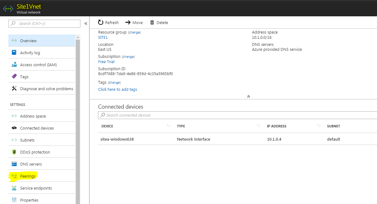
  1. Open the settings of a virtual network and browse into Peerings.
  2. Click Add.
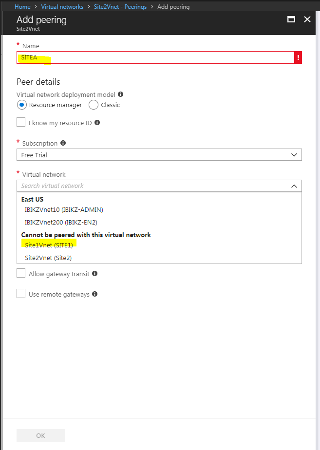
  3. Give the peering connection a name; I try to use the names of the two VNets with the first one being the origin.
  4. You have two ways that you can select the other (remote) VNet. If you know the resource ID of the other VNet, you can paste the resource ID of the other VNet in after checking the box for I Know My Resource ID. You can select a subscription that you have administrative access to, and select a VNet from that subscription.


Create the first VNet peering connection


Create the second VNet peering connection

You should see the peering status of the two VNets switch to Connected after a few minutes. Now virtual machines on each VNet can talk at NIC speeds to virtual machines on the other VNet.
If virtual machines are failing to route with each other then check your network security groups to ensure that the traffic is allowed to and from the required virtual NICs/subnets.

Advanced Configuration

There are four options to note. The first of these disables the VNet peering (and cross-VNet communications) until you are ready to enable it. The other options, used for complex hub/spoke architectures, are as follows:
  • Allow Forwarded Traffic: Allow traffic from a location other than the remote VNet to transit the peering into this VNet.
  • Allow Gateway Transit: All traffic from a VPN/ExpressRoute gateway into this VNet.
  • Use Remote Gateways: Allow virtual machines on this VNet to route via a VPN/ExpressRoute gateway in the other VNet.