Wednesday, 29 June 2016

Controlling User Access to Programs in Windows 7

Controlling User Access

magine this – you have multiple users in your family sharing the same computer and operating system. You don’t want other users of the shared computer to run each and every program that’s installed in Windows 7. Some of the programs which you have installed require knowledge, and you don’t want your kids and other shared members to tinker with the application settings or change the configurations.
The ability to run selected programs for selected users can be achieved in two ways:
1. Choose The User account during Installation of the Application.
2. Tweak the Group Policy Editor and manually Add the Programs which shared users can run
We will discuss both of the above methods in full detail.
Important Note: First make sure that only you have the administrator account and the shared users have a limited user account in Windows7. If one or more of the other user accounts have administrator privileges, he/she might override the settings and configurations which you will create below.

Choose The User account during Installation of the Application
Windows 7 comes with a very useful User Account Control feature which allows you to define which user accounts should have the permission to run a program, when the program is being installed. When you are installing a new application, you will see the following two options:
Install this application for anyone who uses this computer (all users).

Install this application only for me.


If you don’t want other users of your shared computer to use the program you are installing, simply select the radio buttonOnly For me.
That’s it, now only you will be able to use, customize or remove that specific program in Windows7; other shared users will see the following prompt, when they try to run the program from their user accounts:
You don’t have the required permissions to run or remove this Application. Please contact the system administrator
Tweak the Group Policy Editor and manually add the programs which shared users can run.
Note: This section of this tip only applies to Professional editions of Windows. That includes Windows XP Pro, Windows Vista Pro, and Windows 7 Pro. This will not work on Home editions.
If you have already installed all the applications in your computer and don’t want to reinstall them with necessary permissions, you can manually add the programs from the Windows7 Group Policy Editor.
Carefully follow the steps outlined below:

1. Click Windows 7 start menu and type gpedit.msc in the search box. When the search results appear, click the gpedit icon.


2. Clicking the gpedit icon will open Windows Group Policy Editor window.


3. In the left pane, navigate to User Configuration > Administrative Templates folder. You have to first click the small arrow placed next to the User configuration folder and then repeat the same thing for theAdministrative Templates subfolder
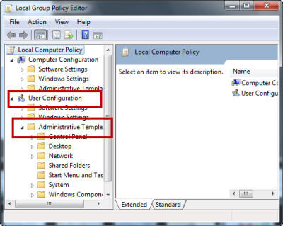

4. When you have reached the Administrative Templates subfolder, click the System subfolder on the left pane.


5. Now switch to the right pane and find the setting which says Run Only Specified Windows Applications.
The current setting for this key should be Not Configured, as shown below:


6. Right click that key and choose Edit


7. This will open a new window where you can define the programs and applications which will have the necessary user permissions.
When the window opens; first select the Enabled button at the top, as shown below:


8. Scroll down and hit the Show button next to List of allowed applications, this will open a small pop up window as shown below:


9. Now you have to type the name of the program which you want other users of the shared computer to be able to use. Type the name of all the common applications e.g. Word.exe, Excel.exe, Firefox.exe one by one in each of the following rows.


When you are done adding all the programs, hit the OK button. Next, hit the Apply button and close the Group Policy Editor window
That’s it, you have just defined the list of all the programs which other users of the same computer may use. Any program that’s not listed in the list of allowed applications will not have the necessary permissions and thus other users won’t be able to run it or entirely remove it from your computer.
Should you want to grant all users the ability to use all the programs installed on your computer, simply navigate to the above mentioned Group policy setting and disable the entire feature.

Saturday, 2 April 2016

Basics of System Administration in Linux

Ubuntu 10.10

Objective 

adduser

sudo
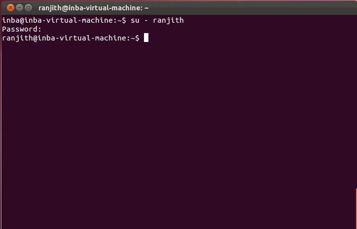
su
sudo -i
usermod
userdel
id
du
df

Summary

 adduser command to create a new user account
 su command to switch from one user to another
 sudo -i  command to change root password 
 usermod command for changing the user account setting
 userdel command to delete the account
 id command to know the information about user ids and group ids
 df command to check the file system size and its availability
 du command to check the space occupied by a file


adduser
 
   The adduser command will create a new user login for us along with authentication
    we can add any user account with the help of sudo command


sudo

   sudo command allows the administrative user to execute a command as a super user.
   The sudo command has many options.

Su
 
   su stands for 'Switch User'
   This commands is useful in switching from current user to another user.


sudo -i

  sudo -i command which is user to change a root password


usermod
 
  usermod Enables a super user or root user to modify the setting of others
  user accounts:
       change the password to no password or empty password
       show the date on which the user
       account will be disabled


userdel

 we can delete the user account permanently with the help of  the userdel command


id

id command is used to check the identities of all the users and groups on the system
To know about the identity of the user, we use id -u
To know about the identity of the group users,it is id -g


df / du

 The df command gives a report on the free space available on the disk.
 The du command gives a report on how much space a file has occupied.


Monday, 28 September 2015

How to Create a WiFi Hotspot Using the Command Prompt

Create a WiFi Hotspot

1
Run. Press the "Windows key" and "R" buttons at the same time. The Run window will pop up.

2
Command Prompt. Type "cmd" in the box then hit "Enter" or OK. The Command Prompt will pop up, with Administrative Privileges.


3
Device Check. Type netsh wlan show drivers in command prompt and press enter.


4
Create. Type netsh wlan set hostednetwork mode=allow ssid=Hotspotname key=password in Command prompt. This will create a Hotspot but it is currently offline.


5
Start. Type netsh wlan start hostednetwork in command prompt to start the hotspot you just created.


6
Stop. Type netsh wlan stop hostednetwork in command prompt to stop the hotspot


7
Details. Type netsh wlan show hostednetwork to check the hotspot status.


8
Internet. To share your internet connection on this hotspot go to the Network and sharing center and click on Change adapter setting. Here right click on the Connection that you use to connect to internet and select properties. In properties go to Sharing tab and check the box "Allow other network users to connect through this computer's internet connection and select the network connection name that is used by your hotspot.(For this check the Network Connection Window and look for Connection which says Microsoft Hosted Network Virtual Adapter). And save it. Now your inter net connection is shared.

Thursday, 5 March 2015

Configuration of Dynamic NAT


Step by Step Configuration 


With dynamic NAT, you must manually define two sets of addresses on your address translation device. One set defines which inside addresses are allowed to be translated (the local addresses), and the other defines what these addresses are to be translated to (the global addresses).


In this example our internal network is using 192.168.0.0 network. We have five public ip address 50.0.0.1 to 50.0.0.5 to use. Router1(1841 Router0) is going to be NAT device. Double click on Router1(1841 Router0) and configure it as given below

Router>enable
Router#configure terminal
Router(config)#hostname R1
R1(config)#interface fastethernet 0/0
R1(config-if)#ip address 192.168.0.1 255.0.0.0
R1(config-if)#no shutdown
R1(config-if)#exit
R1(config)#interface serial 0/0/0
R1(config-if)#ip address 30.0.0.1 255.0.0.0
R1(config-if)#clock rate 64000
R1(config-if)#bandwidth 64
R1(config-if)#no shutdown
R1(config-if)#exit
R1(config)#ip route 0.0.0.0 0.0.0.0 serial 0/0/0
R1(config)#access-list 1 permit 192.168.0.0 0.0.0.255
R1(config)#ip nat pool test 50.0.0.1 50.0.0.5 netmask 255.0.0.0
R1(config)#ip nat inside source list 1 pool test
R1(config)#interface fastEthernet 0/0
R1(config-if)#ip nat inside
R1(config-if)#exit
R1(config)#interface serial 0/0/0
R1(config-if)#ip nat outside
R1(config-if)#exit
R1(config)#exit
Now double click on R2(1841 Router1) and configure it as given below
Router>enable
Router#configure terminal
Router(config)#interface fastEthernet 0/0
Router(config-if)#ip address 20.0.0.1 255.0.0.0
Router(config-if)#no shutdown
Router(config-if)#exit
Router(config)#interface serial 0/0/0
Router(config-if)#ip address 30.0.0.2 255.0.0.0
Router(config-if)#no shutdown
Router(config-if)#exit
Router(config)#ip route 0.0.0.0 0.0.0.0 serial 0/0/0
Router(config)#hostname R2
For testing of NAT go R1 and enable debug for NAT from privilege mode
R1#debug ip nat 
Now go on pc5  and ping to 20.0.0.2
When ICMP ping packet reach to R1. It examines its source address against the access list 1. As this packet is generated form the network of 192.168.0.0 so it will pass the access list. Now router will check NAT pools for free address to translate with this address. Which you can check in the output of debag command in R1
IP NAT debugging is on
NAT: s=192.168.0.7->50.0.0.1, d=20.0.0.2[1]
NAT*: s=20.0.0.2, d=50.0.0.1->192.168.0.7[1]
NAT: s=192.168.0.7->50.0.0.1, d=20.0.0.2[1]
NAT*: s=20.0.0.2, d=50.0.0.1->192.168.0.7[1]
NAT: s=192.168.0.7->50.0.0.1, d=20.0.0.2[1]
NAT*: s=20.0.0.2, d=50.0.0.1->192.168.0.7[1]
NAT: s=192.168.0.7->50.0.0.1, d=20.0.0.2[1]
NAT*: s=20.0.0.2, d=50.0.0.1->192.168.0.7[1]
As you can see in output 192.168.0.5 is translate with 50.0.0.1 before leaving the router.
In real life its best practices to turn off debug after testing so go on Router 1 and turn off debug mode.
R1#no debug ip nat IP NAT debugging is off R1# 


Monday, 2 March 2015

To configure static NAT

Follow this step by step static NAT configure


Configure ip address on PC and Server as given in figure


Now configure R1 exactly given here


Router>enable
Router#configure terminal
Router(config)#hostname R1
R1(config)#interface fastethernet 0/0
R1(config-if)#ip address 10.0.0.1 255.0.0.0
R1(config-if)#no shutdown
R1(config-if)#exit
R1(config)#interface serial 0/0/0
R1(config-if)#ip address 20.0.0.2 255.0.0.0
R1(config-if)#no shutdown
R1(config-if)#exit
R1(config)#ip route 30.0.0.0 255.0.0.0 20.0.0.1
R1(config)#ip nat inside source static 10.0.0.2 50.0.0.1
R1(config)#interface fastEthernet 0/0
R1(config-if)#ip nat inside
R1(config-if)#exit
R1(config)#interface serial 0/0/0
R1(config-if)#ip nat outside
R1(config-if)#exit
R1(config)#

Now configure R0 exactly given here
Router>enable
Router#configure terminal
Router(config)#hostname R0
R0(config)#interface fastethernet 0/0
R0(config-if)#ip address 30.0.0.1 255.0.0.0
R0(config-if)#no shutdown
R0(config-if)#exit
R0(config)#interface serial 0/0/0
R0(config-if)#ip address 20.0.0.1 255.0.0.0
R0(config-if)#clock rate 64000
R0(config-if)#bandwidth 64
R0(config-if)#no shutdown
R0(config-if)#exit
R0(config)#ip route 50.0.0.0 255.0.0.0 20.0.0.2
R0(config)#
As you have seen in configuration there is not direct route for 10.0.0.2. So PC from network of 30.0.0.0 will never know about it. They will access 50.0.0.1 as the web server IP. To test it double click on any computer and ping from 50.0.0.1 and you will get replay.
Packet Tracer PC Command Line 1.0
PC>ping 50.0.0.1
Pinging 50.0.0.1 with 32 bytes of data:
Reply from 50.0.0.1: bytes=32 time=141ms TTL=126
Reply from 50.0.0.1: bytes=32 time=80ms TTL=126
Reply from 50.0.0.1: bytes=32 time=109ms TTL=126
Reply from 50.0.0.1: bytes=32 time=125ms TTL=126

Ping statistics for 50.0.0.1:
    Packets: Sent = 4, Received = 4, Lost = 0 (0% loss),
Approximate round trip times in milli-seconds:
    Minimum = 80ms, Maximum = 141ms, Average = 113ms
Now ping from 10.0.0.2 and you will get destination host unreachable error.
PC>ping 10.0.0.2
Pinging 10.0.0.2 with 32 bytes of data:
Reply from 30.0.0.1: Destination host unreachable.

Ping statistics for 10.0.0.2:
    Packets: Sent = 4, Received = 0, Lost = 4 (100% loss)


Monday, 27 October 2014

Install And Configure Nagios on Ubuntu 14.04 LTS


 Install And Configure Nagios

Nagios is an open source software that can be used for network and infrastructure monitoring. Nagios will monitor servers, switches, applications and services. It alerts the System Administrator when something goes wrong and also alerts back when the issues has been rectified.
Using Nagios, you can:
  • Monitor your entire IT infrastructure.
  • Identify problems before they occur.
  • Know immediately when problems arise.
  • Share availability data with stakeholders.
  • Detect security breaches.
  • Plan and budget for IT upgrades.
  • Reduce downtime and business losses.

Scenario

In this tutorial i am going to use two systems as mentioned below.

Nagios server:

Operating system : Ubuntu 14.04 LTS Server
IP Address       : 192.168.0.2/24

Nagios client:

Operating System : Ubuntu 14.04 Desktop
IP Address       : 192.168.0.107/24
 

Prerequisites

Make sure your server have installed with fully working LAMP stack. If not, follow the below link to install LAMP server On Ubuntu 14.04 and earlier versions.

Install Nagios

Install nagios and nagios plugin using the following command:
sudo apt-get install nagios3 nagios-nrpe-plugin
During installation, you’ll have to answer some simple questions. First, you’ll be asked to configure your mail server to get alerts from your nagios server.
sk@server: ~_001
Select the type of mail configuration:
sk@server: ~_002
Enter the system mail name. It will be automatically selected by the installer. If not, enter it manually.
sk@server: ~_003
Enter the “nagiosadmin” password.
sk@server: ~_004


Re-enter the nagiosadmin password.
sk@server: ~_005

Configure Nagios

After nagios and nagios plugins installation, assign the permissions of www-data directory to nagios user, and set executable permission to the /var/lib/nagios3/ directory.
sudo usermod -a -G nagios www-data
sudo chmod -R +x /var/lib/nagios3/
By default, Nagios won’t check for external commands, just to be on the cautious side.  If you want to be able to use the CGI command interface, you will have to enable this.
To do that, edit file /etc/nagios3/nagios.cfg,
sudo nano /etc/nagios3/nagios.cfg
Find the line,
check_external_commands=0
And change it to:
check_external_commands=1
Save and close the file. Restart nagios service.
sudo /etc/init.d/nagios3 restart

Access Nagios Web console

Open up the web browser and point it to http://ip-address/nagios3. You’ll be asked to enter the username and password. Enter username as nagiosadmin and the password that you’ve created earlier.
New Tab - Mozilla Firefox_001
This is how my Nagios web console looked.
Nagios Core - Mozilla Firefox_002
Click on the Hosts section on the left pane to list of hosts being monitored.
Nagios Core - Mozilla Firefox_003
If you want to see the complete details of a monitoring hosts, click on the respective monitoring hosts in the above window.
Nagios Core - Mozilla Firefox_004
As you see in the above picture, the localhost(Nagios server) itself only is being monitored by default. We have to add the clients to monitor them now.

Add Monitoring targets

Now let us add some clients to monitor by Nagios server. To do that we have to install nrpe and nagios-plugins packages in our monitoring targets.
sudo apt-get install nagios-nrpe-server nagios-plugins

Configure Monitoring targets

Edit /etc/nagios/nrpe.cfg file,
sudo nano /etc/nagios/nrpe.cfg
Add your Nagios server ip address:
[...]
allowed_hosts=127.0.0.1 192.168.1.100
[...]
Start/Restart nrpe service as shown below.
sudo /etc/init.d/nagios-nrpe-server restart
Now, go back to your Nagios server to add the clients to be monitored through nagios server. By default, Debian based systems uses a configuration directory called /etc/nagios3/conf.d/ where nagios3-common, other packages and the local admin can dump or link all object configuration files into.
In the object configuration files, you can define hosts, host groups, contacts, contact groups, services, etc. You can split your object definitions across several config files if you wish, or keep them all in a single config file.
Ex:
cfg_file=/etc/nagios3/objects/commands.cfg
cfg_file=/etc/nagios3/objects/contacts.cfg
cfg_file=/etc/nagios3/objects/timeperiods.cfg
cfg_file=/etc/nagios3/objects/templates.cfg
Also, You can tell Nagios to process all config files (with a .cfg extension) in a particular directory by using the cfg_dir directive.
In this tutorial, I will tell Nagios to process client config files in a particular directory.
Edit /etc/nagios3/nagios.cfg file,
sudo nano /etc/nagios3/nagios.cfg
and uncomment the following line.
[...]
cfg_dir=/etc/nagios3/servers
Create a directory called servers under /etc/nagios3/ location.
sudo mkdir /etc/nagios3/servers
Create config file to the client to be monitored. In my case, I want to monitor my Ubuntu desktop which has IP address 192.168.1.100, and hostname as sk.
sudo nano /etc/nagios3/servers/clients.cfg
Add the following lines:
define host{

use                             generic-host

host_name                       sk

alias                           sk

address                         192.168.1.100

max_check_attempts              5

check_period                    24x7

notification_interval           30

notification_period             24x7

}
Save and close the file.
Here, sk is my Ubuntu 14.04 client host name, and 192.168.1.100 is the IP address of my client.
Restart nagios service.
sudo /etc/init.d/nagios3 restart
Now, open the nagios web console again in the browser and navigate to “Hosts” section in the left pane. You should see the newly added client will be visible there. Click on the host to see if there is anything wrong or alerts. Please note that you have to wait 90 seconds after any changes in your nagios server.
Nagios Core - Mozilla Firefox_005
Click on the monitoring target, you’ll get the detailed output:
Nagios Core - Mozilla Firefox_006
Like this way, you can define more clients by creating a separate config files /etc/nagios3/servers directory for each client.

Define services

We have defined the monitoring host before. Now let us add some services of the monitoring host. For example, to monitor the ssh service, add the following lines shown in red colour in the /etc/nagios3/servers/clients.cfg file.
sudo nano /etc/nagios3/servers/clients.cfg
Add the lines shown in red color:
define host{

use                             generic-host

host_name                       sk

alias                           sk

address                         192.168.1.100

max_check_attempts              5

check_period                    24x7

notification_interval           30

notification_period             24x7

}
define service {
        use                             generic-service
        host_name                       sk
        service_description             SSH
        check_command                   check_ssh
        notifications_enabled           0
        }
Save and close the file. Restart Nagios.
sudo /etc/init.d/nagios3 restart
Now log in to Nagios web console and check for the added services. Navigate to Services section, you should see the ssh service will be available there.
Nagios Core - Mozilla Firefox_007
To know more about object definitions such as Host definitions, service definitions, contact definitions and more please do visit here. This page will describe you the description and format of all nagios object definitions.
That’s it. Happy Monitoring with Nagios!

Reference Links:
For questions please refer to our Q/A forum at : http://ask.unixmen.com/

Wednesday, 3 September 2014

How to configure Site-Site IPSec VPN in Cisco Routers (IOS)

STEPS FOR IPSEC:-


VPN is a network which uses a shared network infrastructure (Internet) which allows a secure access between two networks or securely connects a remote user to his corporate network.
Let's check out here how to configure a Site to Site VPN using a Pre-shared Key in Cisco Routers running Cisco IOS
Let's use a Chennai- office network setup with the following:
Authentication Method: Pre-Shared Key
Hash Algorithm: SHA
Chennai Router External IP : 172.10.10.100
(Peer IP for Branch Network)
Chennai Internal Network: 172.11.1.0/24
Branch Router External IP : 10.1.1.100
(Peer IP for HQ Network)
Branch Internal Network: 10.11.2.0/24
Configuring IKE Policies
Create an IKE Policy
From the global configuration mode, create a new IKE Policy.
VPN-CH(config)# crypto isakmp policy 1
Set the Keep-Alive & Retry intervals
The default Keep-Alive time os 10 seconds and retry when the keep-alive fails is 2 seconds. If you prefer changing this value then do the following else can be ignored
VPN-CH(config-isakmp)# crypto isakmp keepalive 15 retry 3
Specify the Encryption Algorithm
I'm using 3DES encryption method here 
VPN-CH(config-isakmp)# encryption 3des
Specify the HASH Algorithm
I'm using sha hashing algorithm here
VPN-CH(config-isakmp)# hash sha
Set the Authentication Method
We are using Pre-shared key here for Authentication
VPN-CH(config-isakmp)# authentication pre-share
Set the Diffe-Hellman Group Identifier
We are using DH Group-2 (1024)
VPN-CH(config-isakmp)# group 2
Specify SA's lifetime (seconds)
Set the lifetime of the Security Associations in seconds. I'll set it for 24hrs (86400 seconds) here
VPN-CH(config-isakmp)# lifetime 86400
Set Pre-shared Key
The Authentication method we use here is the Pre-Shared key. We should now set this previously agreed shared key (don't exchange on emails. Use your phone,letters or faxes) from the global configuration mode.I'll use a simple pre-shared key "0urVpN" but use more complex key when configuring a production system.
VPN-CH(config)# crypto isakmp key 0urVpN address 10.1.1.100
where 10.1.1.100 is the Peer routers IP Address and "0urVpN" is the pre-shared key.
Define Transformation Set
We set the transformation of ESP-3DES transform and ESP-SHA-HMAC transform to Transformation set 3DES-SHA-HMAC
VPN-CH(config)# crypto ipsec transform-set 3DES-SHA-HMAC esp-3des esp-sha-hmac
VPN-CH(cfg-crypto-trans)# exit
Setup a Crypto ACL
This ACL defines the protected traffic that passes through the VPN tunnel. Customize the ACL as per your organisation needs.
VPN-CH(config)# ip access-list 101 permit ip 172.11.1.0 0.0.0.0 10.11.2.0 0.0.0.0
Create an IPSec Map
Create an IPSec Crypto Map and assign it a Sequence number
VPN-CH(config)# crypto map HQ-BR1-MAP 2 ipsec-isakmp
where 2 is the sequence number and CH-BR1-MAP is the nameof the map.
Set the Network traffic to be protected
Here use the extended ACl created earlier to define the traffic that is protected and passed through the tunnel.
VPN-CH(config-crypto-map)# match address 101
where 101 is the Extended ACL
Set the Peer Address
VPN-CH(config-crypto-map)# set peer 10.1.1.100
Set Transform Set
VPN-CH(config-crypto-map)# set 3DES-SHA-HMAC
Set Perfect Forwarding Secret
VPN-CH(config-crypto-map)# set pfs group 2
Apply Crypto Map to the external Interface
VPN-CH(config)# int fa0/0
VPN-CH(config-if)# crypto map HQ-BR1-MAP
Allow inbound IPSec traffic from the Peer on the external interface
VPN-CH(config)# ip access-list 102 permit udp host 10.1.1.100 any eq isakmp
VPN-CH(config)# ip access-list 102 permit esp host 10.1.1.100 any
That completes the configuration on the Cisco Router at the HQ. Repeat the procedure with only changing
1. The Peer IP in the steps for setting the Pre-shared Key & setting Peer.
2. Modify the ACLs for the protected networks
3. Inbound ACL to allow incoming traffic from peer
To verify the configs, use the following show commands:
Display Crypto IKE Policy
VPN-CH# show crypto isakmp policy
Display Crypto Transform Set
VPN-CH# show crypto ipsec transform-set
Display Crypto Map entries
VPN-CH# show crypto map